Anúncios
What drivers call a “smooth” ride is more than quiet power. It is a coordinated response of motor control, braking, software, and chassis systems working in real time.
This introduction sets expectations: we will unpack the hidden systems that shape everyday drivability. You will learn how the car answers your right foot, how it slows, and why it stays consistent.
The guide previews the main systems: motor and inverter pairing, control software, battery and BMS, regenerative braking, thermal care, and chassis packaging. These elements are tuned to deliver a controllable, quiet, and repeatable experience.
In today’s U.S. market, many drivers test new models through rentals and test drives and notice the difference right away. Smoothness is not accidental — it is system-level design that the modern automotive industry increasingly shapes with electronics-led choices and novel technology.
What “Smooth” Really Means in an Electric Vehicle Driving Experience
Smooth is not just silence. It is how quickly a car responds, how steady it feels, and how predictable stopping feels to the driver.
Anúncios
Instant torque without gear shifts
Many modern powertrains deliver torque instantly because they skip multi-gear shifts. That lack of shift events removes interruptions during acceleration.
Drivers feel a continuous push rather than a series of pauses. This direct torque delivery is a core part of the smooth driving experience.
Anúncios
Low noise, vibration, and harshness (NVH)
NVH stands for noise, vibration, and harshness. In plain terms, it explains why city driving in these cars often feels calmer.
Quiet motors help, but engineers also tune mounts, tires, and cabin insulation to reduce road and tire inputs.
Quiet alone doesn’t equal smooth; high-frequency inverter whine or tire buzz can still make a ride feel rough.
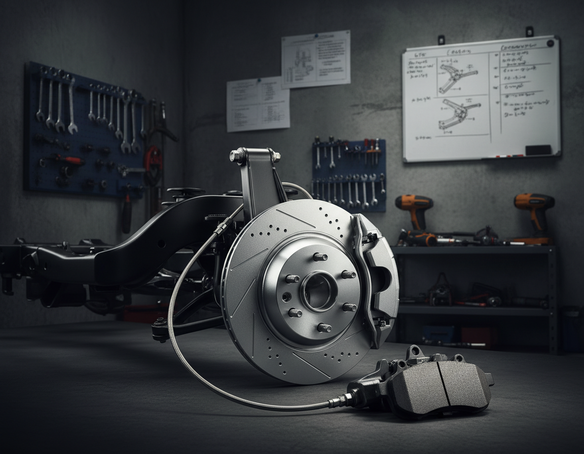
Predictable braking and consistent pedal feel
Smooth braking comes from careful brake blending and consistent pedal mapping. It’s tuning work, not just bigger brakes.
Poorly calibrated torque or regen blending produces jerkiness, even in fast models. Engineers set jerk limits and torque ramp rates to protect traction and comfort.
- Measurable targets: torque ramp rates, jerk limits, and stability constraints.
- Outcome: repeatable performance that matches driver expectations.
For a deeper technical read on how these reliability and drivability goals are tested, see this short primer on driving reliability: driving reliability and smooth ride testing.
EV Basics and Key Terms Engineers Use Every Day
Understanding the basic terms clears up why a model behaves the way it does. These short definitions make conversations about feel, range, and charging easier to follow.
Common acronyms that matter
BEV — Battery Electric Vehicle: runs solely on its battery and motor.
PHEV — Plug‑in Hybrid: a smaller battery plus an engine for longer trips.
HEV — Hybrid: mostly engine-driven with some electric assist.
ICE — Internal Combustion Engine; ZEV — Zero Emissions Vehicle. These labels predict power delivery, braking feel, and charging needs.
Battery terms, regen, and charging
SOC (State of Charge) is the percent charge left. Low SOC can trigger power limits to protect cells and make acceleration feel softer.
SOH (State of Health) shows long‑term capacity. As SOH drops, available power and voltage behavior change, which affects smoothness over time.
kWh describes battery pack energy. More kWh usually means longer range and higher sustained power if cooling and design allow it.
Regenerative braking turns kinetic energy into electrical energy and returns it to the battery, reducing brake wear and improving efficiency.
EVSE and charging levels: Level 1 (120V AC, ~1.3–2.4 kW, ~3–5 miles/hr), Level 2 (208–240V AC, ~3–19 kW, home/work charging in ~8 hours), Level 3/DC fast (200–600V DC+, minutes to ~30 min).
Note: These terms appear constantly in industry conversations and in the information engineers use to diagnose why an EV feels different today than yesterday.
Electric Vehicle Engineering: The System-Level Design Philosophy Behind Smoothness
Delivering a calm, repeatable drive means many subsystems must agree every millisecond.
System-level thinking treats smoothness as an outcome, not a single part. Torque, braking, traction, and thermal limits must coordinate. Software mediates tradeoffs so drivers feel steady response rather than sudden changes.
Cross-domain engineering links mechanical packaging, cooling, battery power, and motor control. A tight battery pack affects cooling needs. Cooling affects available power. Power limits shape torque output. Software ties these elements together.
Controls-first mindset
Design starts with the behavior engineers want: pedal mapping, torque ramps, and brake blending. Hardware is validated against those targets. Calibration and model-based tools like MATLAB/Simulink make this loop repeatable.
Why electronics lead the shift
Modern automotive programs rely more on inverters, sensors, ECUs, and software logic to shape feel. Hiring now favors cross-disciplinary skills across power electronics, controls, embedded software, and validation.
- Practical example: A smooth cold launch depends on thermal limits and battery state as much as on motor size.
- Expectation: Later sections break down motors, inverters, BMS, and controls so you can see how the full system avoids jerk and lag.
| Domain | What it controls | Impact on smoothness |
|---|---|---|
| Battery & BMS | Power delivery, SOC limits | Prevents voltage sag and sudden power cuts |
| Controls & Software | Pedal mapping, torque ramps | Smooth, predictable response to driver inputs |
| Thermal & Mechanical | Cooling, packaging, mount tuning | Maintains consistent performance across conditions |
Electric Motors and Inverters: Where Smooth Power Starts
Power delivery begins at the motor, but the sensation of smoothness comes from how that power is shaped and timed.
Motor basics that influence drivability
A well‑tuned motor gives controllable torque at low speed and a predictable response to driver input.
Minimal oscillations transmitted to the drivetrain reduce shudder and make starts feel effortless.
Inverters and power electronics in plain terms
An inverter converts battery DC into controlled AC for the electric motor. Its switching strategy sets how smoothly current changes and how much audible noise appears.
Good electronics manage current rise rates and shape transitions so the driver feels steady acceleration rather than sudden jumps.
Torque ripple and how engineers minimize it
Torque ripple is a small, repeating torque fluctuation that can cause buzz or tremor. Engineers cut ripple through careful motor design and control algorithms.
Design choices, rotor geometry, and control loops all work together to reduce that subtle shudder.
Thermal limits and consistent acceleration
When motors or inverters heat up, the system may reduce available power to protect components.
That thermal protection preserves long‑term performance but can change short‑term acceleration feel during repeated hard pulls or long climbs.
Efficiency benefits too: smoother control avoids wasted oscillations and lowers losses, so refinement often improves range and overall performance across systems.
Motor Control Software: The “Invisible Hand” That Makes Acceleration Feel Effortless
Behind every seamless acceleration is software that quietly shapes how power reaches the road. This layer turns a pedal press into a safe, predictable torque request before the motor ever spins.
Torque request pipeline: Pedal input becomes a requested torque. Traction and stability constraints reshape that request so the final command matches grip and safety limits. This control pipeline prevents sudden surges or cutbacks that drivers notice as jerk.
How traction and calibration protect feel
Traction and stability systems stop wheel slip quickly. They smooth power by trimming torque rather than cutting it in big steps. That keeps acceleration steady during low-grip or high-load moments.
Calibration is the “feel” layer. Pedal maps, ramp rates, and drive modes (Eco/Normal/Sport) set how fast power arrives and how it tails off. The same hardware can feel sharp or gentle depending on mapping choices.
Embedded systems that coordinate actions
ECUs share messages over CAN so braking, thermal, and powertrain modules agree in real time. Good teams use embedded C, model-based tools, and repeated calibration cycles to tune these systems. Over time, that iterative process is what makes modern vehicles feel refined and predictable for daily mobility.
Battery Packs and Battery Management Systems That Keep Power Consistent
Think of the battery pack as a tank and a pump: it stores energy and supplies bursts of power on demand. Smoothness depends on steady voltage and current delivery when load changes suddenly.
Why the BMS matters for consistent power
Battery management systems monitor cell voltages, estimate SOC and SOH, and enforce safe limits. This keeps power delivery predictable and protects pack life.
Voltage sag and protective power limits
Voltage sag is a temporary drop under high demand. It can feel like reduced punch when the pack can’t keep voltage up.
Power limits exist to avoid damage, overheating, or unsafe conditions. The BMS trims output rather than letting cells fail.
Cell balancing: passive vs active
Balancing keeps cells at similar SOC so the pack uses capacity evenly. Passive schemes bleed excess charge; active systems move energy between cells for better efficiency and usable range.
Degradation and the driver experience
As SOH declines, peak power and usable energy fall. A good system manages this so the car feels consistent over time.
Driver takeaway: If your car feels softer at 20% SOC, that is often a BMS protection strategy, not a defect. Learn more about practical BMS design in this primer: battery management systems explained.
| Item | What it does | Impact on smoothness |
|---|---|---|
| Pack (cells) | Stores energy, supplies power | Stable voltage prevents sudden loss of acceleration |
| BMS | Monitors SOC/SOH, enforces limits, balances cells | Keeps power delivery predictable and protects longevity |
| Balancing method | Passive vs active balancing | Active balancing preserves capacity and consistent feel |
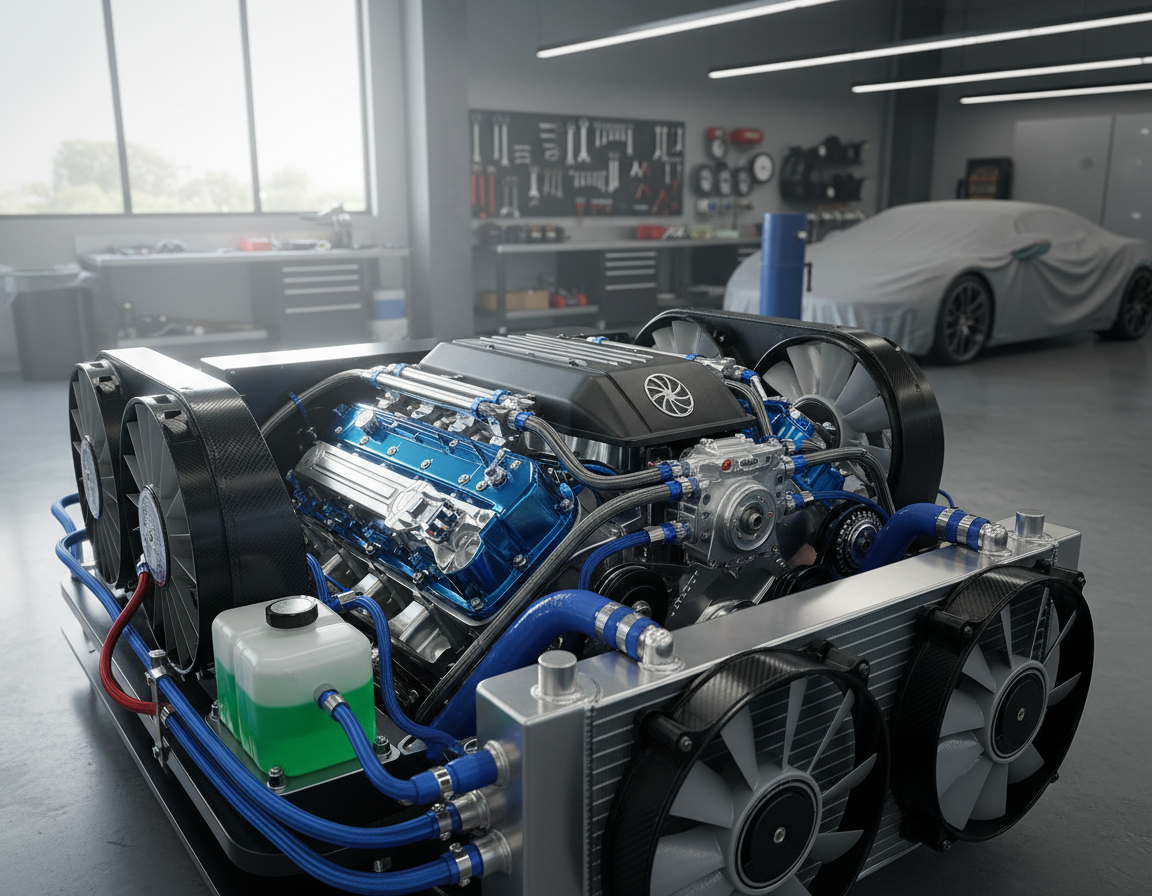
Thermal Management Engineering for Battery, Motor, and Electronics
Temperature control is the hidden reason driving feel stays steady across seasons and traffic.
Keeping performance predictable across seasons and driving conditions
Thermal systems let a car deliver similar power in summer heat, winter cold, or stop‑and‑go traffic.
When the pack is warm, peak power and regen availability are higher. Cold packs often reduce output until they warm.
Thermal constraints during charging and their effect on drivability afterward
Fast charging creates heat in cells and power electronics. The BMS and coolant loops limit charging speed to protect cells and to keep energy delivery safe.
After a DC fast charge, the car may temporarily limit torque or regen until temperatures settle. That keeps repeatable feel and prevents damage.
How motor and electronics temperature shape behavior
Motors and inverters have thermal caps. Control software uses thermal models to trim torque ramps and prevent overheating.
This coordinated design preserves long‑term performance and reduces unexpected cutbacks during hard driving.
- Good thermal layout improves efficiency by keeping parts in optimal ranges.
- Cooling strategies (liquid loops, heat pipes) balance heat across pack and electronics.
- Seasonal strategies warm packs gently to restore regen and acceleration predictability.
Practical U.S. use case: after a quick DC fast charge on a road trip, expect managed power and softer regen for a short distance until the thermal loop stabilizes. That tradeoff protects cells while keeping the driving feel consistent in the wider world.
Regenerative Braking Systems That Blend Stopping Power With Energy Recovery
Regenerative systems reclaim motion and must be carefully mixed with friction brakes to feel natural.
How regen works in plain English: during deceleration the motor becomes a generator. It converts motion into electrical energy and returns some charge to the pack. This reduces wear on the friction brakes and can improve overall efficiency.
Brake blending: a coordination problem
Friction brakes and regenerative braking must share the work so the vehicle slows predictably. Control software decides how much regen is allowed based on speed, SOC, and temperature.
When regen is limited—for example when the battery is full or cold—the friction system steps in seamlessly to preserve pedal feel.
One‑pedal tuning and pedal feel
Manufacturers tune lift‑off decel differently. Some vehicles give strong coast‑down on release; others use a gentle ramp so drivers rely on the brake pedal more.
These choices, plus SOC limits and ramp rates, explain why the same action feels different across models.
Reducing jerk near a stop
Low‑speed handoff from regen to friction brakes is tricky. Small timing errors or abrupt torque cuts produce noticeable jerk around 5 mph to 0 mph.
Engineers smooth that zone by limiting torque‑ramp rates and adding short reaction deadbands so stops feel consistent.
“Good brake blending is more about predictability than maximum recovery.”
| Aspect | What it affects | Driver impact |
|---|---|---|
| Regen availability | Energy recovered, decel strength | More recovery can mean stronger coast-down |
| Blending logic | How regen and friction share load | Smoother, more predictable stopping feel |
| Battery state / temp | Limits on regen power | May force friction use to keep feel consistent |
Realistic takeaway: regen helps recover energy and can polish the braking experience, but reliable feel depends on careful control and fallback to friction brakes when limits are reached.
Charging and Power Delivery: How Energy Enters the Vehicle Smoothly and Safely
Charging is a managed exchange: the station and pack negotiate limits before power flows. That handshake protects cells and shapes how the car behaves after a session.
Level 1, Level 2, and Level 3 tradeoffs for daily use
Level 1 — 120V AC; ~1.3–2.4 kW; adds ~3–5 miles per hour. Good for light daily driving and overnight top-ups.
Level 2 — 208–240V AC; ~3–19 kW; typically fills a pack in ~8 hours and suits home or workplace charging.
Level 3 / DC fast — ~200–600V DC+; can recharge in ~30 minutes for road trips or tight turnarounds.
EVSE communication and safety
EVSE does more than supply energy. It runs a safety check, verifies connectors, and exchanges signals with the pack before any current flows.
“A secure handshake prevents unsafe currents and keeps charging predictable.”
Speed, heat, and battery management constraints
Faster charging raises thermal load. The battery management system may taper power to protect cells and extend life.
This thermal state can affect regen and peak power briefly after a fast charge. Choosing the right charging approach helps balance convenience with long‑term health.
| Level | Voltage / Power | Best use |
|---|---|---|
| Level 1 | 120V AC / 1.3–2.4 kW | Overnight home top‑ups, light daily miles |
| Level 2 | 208–240V AC / 3–19 kW | Routine home/work charging, full overnight fills |
| Level 3 (DC fast) | ~200–600V DC / high kW | Road trips and quick turnarounds; higher thermal stress |
Takeaway: match charging speed to your routine. Thoughtful charging preserves battery health, keeps energy delivery consistent, and supports smooth drivability.
Virtual Prototyping and Simulation Tools That Refine Ride and Efficiency
Simulation lets teams test hundreds of drivetrain and thermal scenarios before a single prototype is built.
Virtual prototyping speeds development by validating powertrain, thermal, and control strategies in software. This early testing reduces surprises and lowers costs while improving final performance.
How simulation accelerates testing before physical prototypes
Teams run control maps and torque delivery cases virtually to spot jerk, thermal limits, or traction issues. That saves time on the track and shortens iteration cycles.
- Validate subsystems before hardware exists.
- Tune pedal and regen logic across many conditions.
- Catch thermal and power tradeoffs early in the design process.
Aerodynamics optimization to reduce drag and extend driving range
Computational airflow tools analyze shapes to cut drag. Less drag means quieter cruising, better efficiency, and more stable high‑speed behavior for drivers.
Crashworthiness and structural integrity modeling to meet safety expectations
Advanced simulations predict how structures absorb impact. Better structural design also changes how NVH travels through the body, so stiffness and crash paths affect ride refinement.
Mass reduction without sacrificing performance or manufacturability
Virtual trade studies test lighter layouts and new materials. Reducing mass can boost responsiveness and efficiency, but teams must preserve manufacturability and safety targets.
“Simulation shortens the development loop, but real road testing remains essential to confirm feel and durability.”
Bottom line: these technologies do not replace real tests. They help engineers converge faster on a smooth, efficient design by giving more information earlier in the process.
Chassis, Weight Distribution, and Packaging: The Mechanical Side of EV Smoothness
Battery location and mass distribution shape how a car leans, turns, and absorbs bumps. A low center of gravity helps a vehicle feel planted, reduces body roll, and improves driver confidence in corners.
Low center of gravity and ride behavior
The battery pack usually sits low in the floor. That arrangement lowers roll and keeps the cabin steady during quick direction changes.
Result: tighter tracking with less lateral pitch, so everyday maneuvers feel composed.
Suspension tuning for heavier curb weights
Higher curb mass means springs and dampers must be tuned for both comfort and control. Engineers select rates and damping curves to manage squat, dive, and body motion.
Good tuning hides weight while preserving ride compliance over bumps.
Braking, stability, and packaging tradeoffs
Packing motors, cooling lines, and structural components affects stiffness and noise paths. Placement influences how suspension and tires work together.
Braking and stability are integrated problems: friction brakes, regen, tires, and electronic control must cooperate so stops and traction feel predictable.
Practical takeaway: two vehicles with the same powertrain can deliver different perceived refinement if one has better damping control and more cohesive brake‑traction integration. Chassis design is as vital to smoothness as the power components.
Safety, Reliability, and Validation: The Engineering Process You Don’t See
Validation work makes sure a refined feel survives real-world abuse and odd moments. This unseen effort ties safety, reliability, and consistent performance into one disciplined program.

Testing, validation, and certification in design
Teams run edge-case scenarios: potholes, emergency braking, extreme temperatures, repeated fast charging, and degraded battery states. Each case checks that the ride stays steady and predictable.
Certification proves the product meets legal and market expectations before it ships.
Functional safety and fault handling
Control and electrical systems are built to fail gracefully. Sensors, ECUs, and power electronics detect faults, hand off control, and keep brakes and steering stable.
Durability across batteries, power electronics, and thermal loops
Durability tests stress the pack, inverters, and cooling systems over years of cycles. That work preserves pedal feel and braking consistency as components age.
“The smoothest models are often those backed by the strictest testing culture.”
Conclusion
Conclusion
Smoothness is a systems outcome: control software, motors, inverters, BMS, braking, and thermal loops must all agree to deliver a calm, predictable drive. This is the heart of electric vehicle engineering and why feel varies across models.
In practice, smooth means instant but controllable response, low cabin buzz, predictable braking, and stable behavior across temperatures and state of charge.
Key contributors are torque control, calibration and drive modes, BMS power limits, brake blending, and chassis tuning. When you test a new car, try low‑speed parking, a moderate acceleration, regen handoffs near a stop, and consistency after a fast charge.
As mobility shifts in the United States and around the world, software and electronics keep improving refinement. Visit our website for more guides and technical information on BMS, charging, and simulation.